Friction refers to the force that resists movement among various surfaces. The heat generated in the contact point through constant friction softens the materials on the surfaces.
And friction welding is a technique of joining similar or dissimilar materials by developing heat through friction.
Welders can combine similar and dissimilar materials with different melting points through the friction welding process. Its ability to join different materials, consistent quality, limited shortcomings, time and cost effectiveness all have helped it to gain enormous traction in the industrial world.
This article will focus on the basics of friction welding, such as its working procedure, types, advantages, etc.
A Brief Overview of Friction Welding

The friction welding process involves bringing the surfaces of the materials into direct contact of induce friction. When two components contact each other in a rotational force, a higher mechanical pressure is created.
This mechanical motion excludes polluted materials from metal surfaces and creates a strong bond between them. That’s how, friction welding generates a stronger bond than other types of welding mechanisms.
Friction welding differs from traditional fusion welding process in term of using filler metal. Fusion welding process adds fillers to attach materials where friction welding is involves two pieces of metal rotate in an axial direction to generate heat and fuse together. It uses no filler rod in friction process.
The friction stage and forge stage are two vital stages that complete this procedure. The entire process is machine-controlled. So, welders can monitor and control the process, creating unmatchable and un breakable joint.
Working Process of Friction Welding
Every type of surface, including metal and non-metal surfaces, has holes or bumps on their surfaces. In physics, these holes are familiar as asperity. Even smooth and polished surfaces have asperities.
When you place two different surfaces on top of each other and rotate them swiftly in an axial direction, friction will take place among the asperities of the two surfaces. In turn the frictional interaction between asperities generates heat.
The more friction means the more heat. Here you must consider the direction between metal components be axially align to each other.
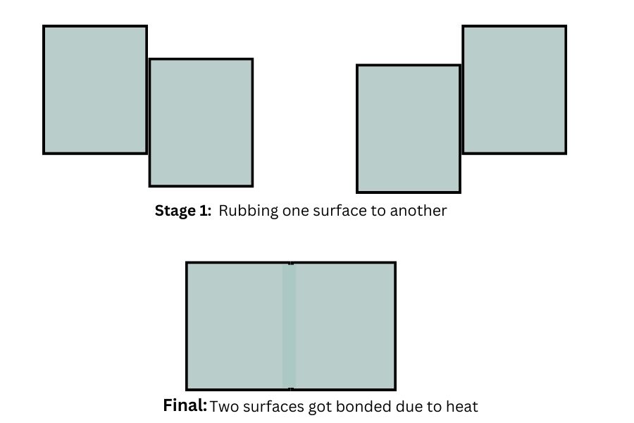
After obtaining the targeted temperature in the metals interface, welders apply an external pressure through a machine. This machine evenly distributes the pressure to melt and permanently fuse the materials at the contact point. This is the simple working principle of friction welding.
Braking – reduction in friction welding is a critical aspect that contributes to the efficiency and success of the welding process. By carefully managing the braking system, operators can regulate the pressure and rotational speed, controlling the amount of friction-induced heat.
Achieving optimal braking reduction ensures a balance between heat generation and dissipation, preventing overheating and material damage during the welding process. This fine-tuned control enhances the overall quality of friction welding, resulting in strong, reliable joints with minimal distortion or defects.
What Metals To Join With Friction Welding
Friction welding is a versatile process that can be used to join a variety of metals, both similar and dissimilar. Some of the common metals that can be joined using friction welding include:
- Steel Alloys:
- Carbon steel
- Alloy steel
- Stainless Steels:
- Austenitic stainless steel
- Martensitic stainless steel
- Ferritic stainless steel
- Aluminum Alloys:
- 1000 series (pure aluminum)
- 2000 series (aluminum-copper alloys)
- 6000 series (aluminum-magnesium-silicon alloys)
- Copper and Copper Alloys:
- Pure copper
- Brass (copper-zinc alloy)
- Titanium Alloys:
- Commercially pure titanium
- Titanium alloys with aluminum, vanadium, or other elements
- Nickel Alloys:
- Inconel alloys
- Monel alloys
- Hastelloy alloys
- Magnesium Alloys:
- AZ series alloys
- AM series alloys
- Super Alloys:
- Materials such as Nimonic, Waspaloy, etc., used in high-temperature and aerospace applications.
- Other Alloys:
- Various other non-ferrous alloys used in specific applications.
What Are The Types Of Friction Welding?
The process of heat generation and mixing the materials depends on the type of friction welding implemented. That’s why it is crucial to have an overall idea about the types of friction welding.
Here is a brief overview of each type of friction welding:
1. Friction Stir Welding (FSW):
Friction stir welding refers to a solid-state joining mechanism. The process requires a non-consumable tool that has a profiled pin and a cylindrical shoulder to join the working surfaces.
After placing the two workpieces in the tool side by side, the tool rotates at a high speed in the middle of the joint of the workpieces.
It also generates a hole until the cylindrical shoulder rests on the workpieces’ surface. The high speed rotation generates heat that softens the metals, but it does not melt them. The temperature can range from 900 to 1300 Celsius.
Later, Dynamic recrystallization takes place and joins the two different workpieces.
Basic Principles In FSW
The key steps in the FSW process are as follows:
- Tool Rotation: A specially designed cylindrical or tapered tool with a shoulder and a pin is rotated at a constant speed.
- Tool Plunging: The rotating tool is plunged into the joint between the two workpieces, creating friction between the tool and the material.
- Heat Generation: The frictional heat softens the material without reaching its melting point. The softened material forms a plasticized region around the rotating tool.
- Material Stirring: The rotating tool, with its pin and shoulder, stirs and mixes the softened material in the plasticized zone. This action breaks down the material’s structure and facilitates metallurgical bonding between the workpieces.
- Tool Traverse: The tool is moved along the joint line, progressively welding the materials together.
- Cooling and Solidification: As the tool moves away, the plasticized material cools and solidifies, creating a solid-state weld joint.
Major form of application:
- Shipbuilding and Marine
- Aerospace
- Railway industry
- Automotive
- Electronics
2. Friction Stir Spot Welding (FSSW):
FSSW (Friction Stir Spot Welding) is basically a developed and modified version of FSW, involving a non-consumable tool with a probe and shoulder. This process involves no linear movement like FSW.
Basic Principles In FSSW
The entire process involves three stages:
- Rotating and Plunging:
In the initial stage, the tool rotates until its shoulder reaches the workpiece’s top surface. This rotation also generates heat that softens the surface materials. Therefore, the tool can easily plunge into the workpiece to a pre-determined depth.
- Stirring stage:
the tool keeps rotating and generating heat. Therefore, the constant rotation further softens the materials, mixes and joins them.
- Extraction:
After creating the bond between the workpieces, the tool is taken back. This phase is named as extraction.
Major applications:
- Railway industry
- Shipbuilding and Marine
- Aerospace
3. Linear Friction Welding (LFW):
LFW is another solid-state joining technique. Welders mainly use this method to join higher-temperature metal properties with lower thermal conductivities (for example: titanium alloys).
In this procedure, the tool does not rotate, rather it moves laterally. The whole procedure involves high-level pressure to soften and mix the materials.
Basic Principles In LFW:
The basic principle of friction welding involves several key steps:
- Contact and Rotation: Two workpieces to be joined are brought into contact with each other under pressure. One of the workpieces is rotated relative to the other.
- Frictional Heating: The rotational motion generates frictional heat at the interface between the two workpieces. This heat softens the material without reaching its melting point, creating a plasticized or semi-solid state in the contact zone.
- Material Upset: Once the material reaches a plasticized state, the rotation is stopped, and axial pressure is applied. The non-rotating workpiece is forced against the rotating one, causing material to flow and upset in the plasticized region.
- Joint Formation: As the upset material cools and solidifies, it forms a strong metallurgical bond between the workpieces, creating a solid-state weld joint.
Major form of application:
- Automotive
- Shipbuilding
- Railway industry
- Oil, gas, and energy construction.
4. Rotary Friction Welding (RFW):
Rotary friction welding involves two work different workpieces: One is static and another is on the rotating spindle. When the rotating spindle moves, friction takes place between the contacting surfaces of two workpieces.
The generated heat from the friction softens the materials. Besides, it excludes impurities and the oxidized layer from the surfaces. As a result, no new oxide layer can form. Later, professionals implement forge force to create a strong bond between the surfaces.
Basic Principles
The basic principle of Rotary Friction Welding involves several key steps:
- Contact and Rotation: Two cylindrical workpieces, often of different materials or diameters, are brought into contact with each other. One of the workpieces is held stationary, while the other is rotated.
- Frictional Heating: The rotating workpiece generates frictional heat at the interface between the two parts. This heat softens the material in the contact zone without reaching its melting point, creating a plasticized or semi-solid state.
- Material Upset: Once the material reaches the plasticized state, the rotation is stopped, and axial pressure is applied. The non-rotating workpiece is forced against the rotating one, causing material to flow and upset in the plasticized region.
- Flash Formation and Removal (optional): In some cases, a thin layer of material, called flash, may be formed at the joint interface. This flash can be removed by machining or other means, leaving a clean, solid-state weld joint.
- Joint Formation: As the upset material cools and solidifies, it forms a metallurgical bond between the workpieces, creating a strong, solid-state weld joint.
Major form of application:
- Turbine shafts
- Automotive parts
- Piston rods
- Cutting tools
- Copper-aluminum electrical connections
5. Friction Taper Plug Welding:
The main objectives of friction taper plug welding (FTPW) are to repair holes that are not drilled correctly and fix cracks, and other defects in steel plates or pipes. The process involves drilling a tapered hole on the defected area of the plate. A tapered hole refers to a hole where the starting and ending diameter of the hole is different.
Next, professionals insert a tapered plug into the hole and its conical surface is attached to the hole’s surface.
Basic Principles Of FTPQ
The basic principle of Friction Taper Plug Welding involves the following steps:
- Contact and Rotation: Two tubes or pipes to be joined are brought into contact with each other. One of the tubes is internally fitted with a tapered plug, and the other tube is held stationary while the assembly is rotated.
- Frictional Heating: The rotating assembly generates frictional heat at the interface between the plug and the stationary tube. This heat softens the material in the contact zone without reaching its melting point, creating a plasticized or semi-solid state.
- Material Upset and Taper Compression: Once the material reaches the plasticized state, the rotation is stopped, and axial pressure is applied. The tapered plug is forced into the stationary tube, causing material to flow and upset in the plasticized region. Simultaneously, the taper provides a compressive force that aids in the consolidation of the material.
- Joint Formation: As the upset material cools and solidifies, it forms a metallurgical bond between the tapered plug and the stationary tube, creating a strong, solid-state weld joint. The resulting joint typically has a gradually changing diameter due to the taper.
Major applications:
- Aerospace
- Oil and Gas fields
- Automotive industry
- General Manufacturing
6. Core flow:
Core Flow is an innovative, sub-surface fabricating method invented by TWI. This process combines both friction stir channeling (FSC) and friction stir welding (FSW). In a single manufacturing step, it incorporates subsurface channel networks into two- or three-dimensional solid parts. TWI
Without sacrificing surface integrity, it permits the incorporation of interior components like heat pipes, cooling channels, and sensor networks.
What are the positive and negative sides of friction weld?
The friction welding process includes numerous benefits and drawbacks of friction welding. Major positive and negative sides of friction weld are as follows:
Major positive sides of friction welding:
- Friction welding is a faster, more effective, and environment-friendly welding process than the conventional ones.
- The process is free from difficulties related to fusion welding, such as solidification cracks, pores, etc.
- It requires no external filler metal and shielding gas
- For both similar and dissimilar material welding, the friction welding process is the best solution
- It requires minimal surface preparation
Major negative sides of friction welding:
- It is not ideal for combining thicker materials made from fragile components like aluminum and stainless steel.
- The process requires an adequate ventilation system to prevent overheating problems due to intense heat generation.
- Metals are easy to heat up, but time-consuming to cool down. Considering this fact, Friction welding can be a bit more time-consuming than the conventional one.
- The process requires skilled persons to conduct the processes.
Inertia Vs Friction Welding
Though many individuals synonymously use the terms friction welding and inertia welding, the latter is a type of friction welding. More specifically, inertia welding is similar to rotary friction welding and earned its name from its rotating style.
The main differences between these two welding processes are as follows:
- Source of Energy:
In friction welding, conventional energy sources such as hydraulic or electric motors provide energy.
The inertia welding process uses a rotating flywheel that preserves kinetic energy. It is not possible to stop the flywheel until all kinetic energy converts to heat.
- Operational Steps:
The friction welding requires axial alignment of both components. One workpiece installed in the spindle rotates where another component remains stable.
The movable clamps push it forward to induce friction and generate heat. After achieving the targeted temperature, the implemented brake stops the orbital motion.
Increased axial forces then join the materials after metals are solidified. Here mechanical motion from the machine converts into a orbital motion, resulting in fusion of two metals together.
The inertia welding process also involves two workpieces: one is stationary and another is with a flywheel. The flywheel increases angular velocity to preserve sufficient kinetic energy.
After storing the energy, two component contact to each other under higher pressure. The process involves no brake; rather the weld itself serves as the brake to stop the flywheel to transform the kinetic energy to heat.
- Heat Production: In the friction welding process, heat production takes place due to the rubbing of the working surfaces. In contrast, heat generation in the Inertia welding process happens because of the immediate effects of the two surfaces, instead of friction.
- Types of Joint: Welders can attach both similar and dissimilar materials through friction welding. It can involve different joint types such as T-joints, butt joints, lap joints, etc. In contrast, Inertia welding is prominent for joining similar materials with the same diameters.
How fast is friction welding?
The speed of friction welding can vary depending on the specific type of friction welding being used, the materials involved, and the size and configuration of the components being joined. Here are some general considerations:
- Inertia Friction Welding (IFW): Inertia friction welding is known for its high speed. The rotational speed of the rotating workpiece can reach several thousand revolutions per minute (RPM), allowing for rapid heating and subsequent welding.
- Direct Drive Friction Welding (DDFW): Direct drive friction welding, or linear friction welding, involves reciprocating motion. The oscillation frequency and amplitude can be adjusted to control the heating and forging process. While it may not reach the same rotational speeds as IFW, DDFW can still be a relatively fast process.
- Friction Stir Welding (FSW): Friction stir welding involves the rotation of a non-consumable tool. The rotation speed is typically lower than in inertia friction welding, often in the range of a few hundred to a few thousand RPM. The traverse speed (how fast the tool moves along the joint line) can also affect the overall process speed.
- Specific Applications: The speed of friction welding can also be influenced by the specific requirements of the application. For example, smaller components might allow for faster welding speeds than larger or more complex structures.
What are the defects of friction welds?
While friction welding is generally a reliable process, like any welding method, it can be susceptible to certain defects. Common defects in friction welds include:
- Flash: Flash is excess material that may be extruded or expelled from the joint during the welding process.
- Upset Irregularities: Inconsistencies in the upset or forging process can result in uneven material flow and upset formation. This can lead to irregularities in the joint, affecting its strength and integrity.
- Incomplete Bonding: In some cases, incomplete bonding may occur, leading to a weak or incomplete joint. This can be caused by factors such as insufficient heat generation, inadequate pressure, or improper material preparation.
- Material Expulsion: During the welding process, especially in certain configurations, there may be expulsion of molten or softened material from the joint area. This can result in a weaker weld or create surface irregularities.
- Porosity: In some instances, porosity may occur in the weld due to the entrapment of gases during the welding process. This can affect the mechanical properties of the joint.
- Cracks: Cracks may develop in the weld zone, particularly if there are issues with material preparation, excessive heat, or rapid cooling. Cracking can compromise the integrity of the joint.
- Tungsten Inclusions (for Inertia Friction Welding): In inertia friction welding, tungsten inclusions from the tool may occur in the weld if the tool is not properly maintained or if there are issues with tool integrity.
Frequently Asked Questions
1. What Are The Two Basic Types Of Friction Welding?
1. Inertia Friction Welding (IFW)
2. Direct Drive Friction Welding (DDFW)
2. What is friction welding called?
1. Friction Welding
2. Inertia Friction Welding (IFW)
3. Friction Stir Welding (FSW)
4. Friction Taper Plug Welding (FTPW) &
5. Spin Welding
Last Words
Friction welding is a member of solid state welding techniques. It produces top-notch outcomes with minimal defections. Industrial manufacturers are expanding the use of this process, indicating its future leadership in industrial applications.
This article has focused on the basics of friction welding and other relevant information. I hope the readers will find the information valuable for their practical use.
Sources
- en.wikipedia.org/wiki/Friction_welding#:~:text=Friction%20welding%20(FWR)%20is%20a,displace%20and%20fuse%20the%20materials.
- interestingengineering.com/innovation/friction-welding-process-types-and-advantages